37 Degree Flare Flange
HOME / 37 Degree Flare Flange
37 Degree Flare Flange
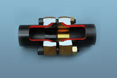
37 Degree Flare Flange is a system based on flaring the pipe ends to 37 degree and utilizing internal cones (with O-rings) and flanges for the assembly.
The flange is slipped onto the pipe before flaring. After flaring, the cones are located into the pipe. The O-Ring face cone with the O-Ring seal mates with the flat face cone. Both the cones have back-up O-Rings. Bolting the connection together draws the flared pipe and cone in contact with each other providing an elastomer seal at the flare and at the face.
The flanges can be rotated prior to bolting thus eliminating the need to be concerned about the axis of the pipe on which the fitter aligns the flange holes. At times, it also allows the flange cap screws to be installed in more confined spaces. Pipe flaring is an easy to implement process. Learn more on how flaring is done.
37 Degree flare flange system is used for pipes of sizes ranging from ½” to 8”. This is considered to be a fool proof solution for comparatively thin walled pipes. They can withstand pressures of up to 6000 psi. The standard connection styles offered conform to SAE Cd 61 (ISO 6162 -1), SAE Cd 62 (ISO 6162-2), ISO 6164 4-bolt flanges along with TMI® 8-bolt, 9-bolt proprietary flanges. Other flange patterns are also be available. TMI has in-house developed a Flaring machine to meet the required standard of 37 Degree flare flange. The operation is simple and the machine operator needs basic training to operate the equipment which will be provided by our in house installation team. Learn more about the flaring machine.
37 Degree Flare Flange is extensively used in Hydraulic Applications in many industries
Please refer to its applications in
37 Degree Flare Flange has the following certifications and approvals:
Instructions to install a 37 Degree Flare Flange Connection
Step 1
Pipe supplied with butt end machined along with an annular groove on the outside diameter using a grooving machine.
Step 2
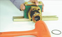
Pipe is to protrude to the stop on the die. Lubricate the flaring cone, start the flaring machine, flare the pipe end until fully formed against the die. Stop the machine; remove the pipe from the die.
Step 3
Clean and visually inspect the flare. The surface of the flare should be smooth and free of any defects.
Step 4
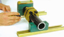
Select the correct pipe cone style from the catalogue. Insert pipe cone into the flared end of the pipe (use rubber hammer if required).
Step 5
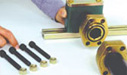
Select the required bolting hardware from Section R of the catalogue.
Step 6
Tighten bolts to the torque values specified. Always tighten bolts in a cross-over sequence and ensure that the flanges are parallel.
Alternatively send us an email to info@cenergyoffshore.com to avail physical copy of the Catalogue.