Pune, Maharashtra
2019
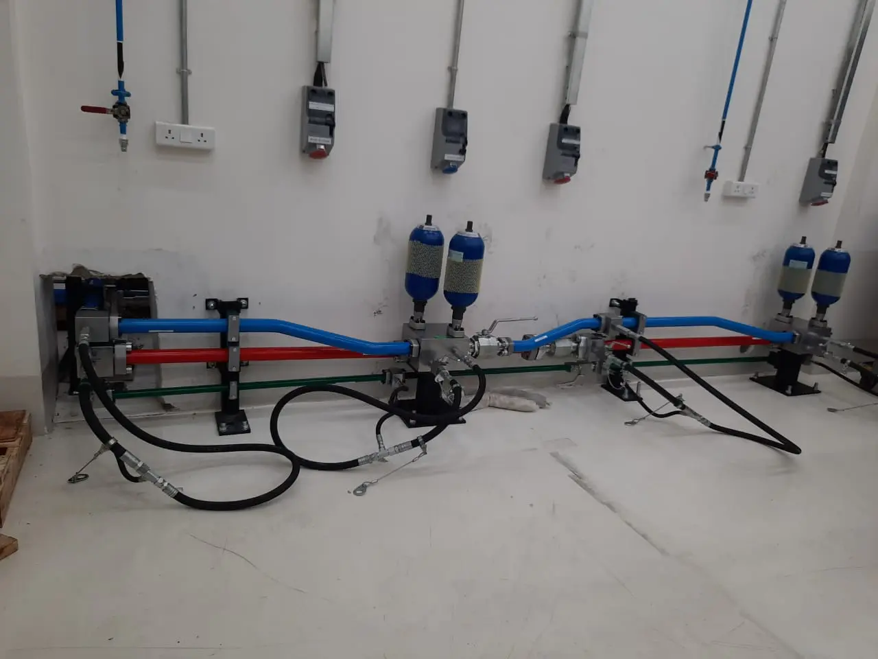
Cummins, a leading engine manufacturer, was establishing a new Fatigue Laboratory within its newly constructed Applied Mechanics Lab at its R&D facility in India. As part of the laboratory, Cummins required hydraulic piping for a Block and Head Test Rig. The test rig generated significant vibration during operation, creating a demanding environment for hydraulic piping where connection integrity, leak prevention and long-term reliability were critical.
The existing laboratory had experienced issues associated with conventional welded hydraulic piping. Cummins therefore sought a more reliable piping solution that could withstand the demanding operating conditions of the new test facility. Cenergy Offshore, a pioneer in non-welded hydraulic piping technology in the region, was selected to design, supply, install and commission the complete hydraulic piping system.
The primary challenge was to develop a hydraulic piping system capable of operating reliably in a high-vibration test environment. The piping had to maintain leak-tight connections over repeated testing cycles while also accommodating hydraulic accumulators and associated equipment within the available laboratory space.
The project comprised two separate hydraulic systems: a) HBBB Test Rig: 5,800 PSI system pressure b) Load Frame System: 3,000 PSI system pressure
The customer also required the new piping system to address the reliability issues experienced with welded joints in the previous laboratory.
The solution therefore needed to provide:
Reliable high-pressure connections
Resistance to vibration-related stresses
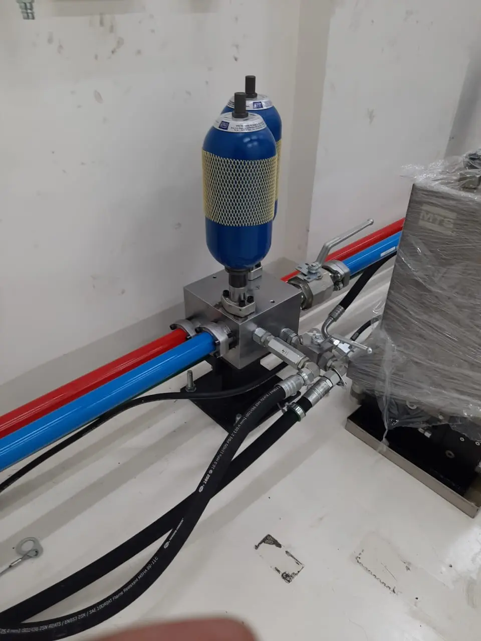
Proper support for the piping and accumulators
Efficient use of the available laboratory space
High hydraulic cleanliness
A pre-engineered installation approach suitable for the new facility
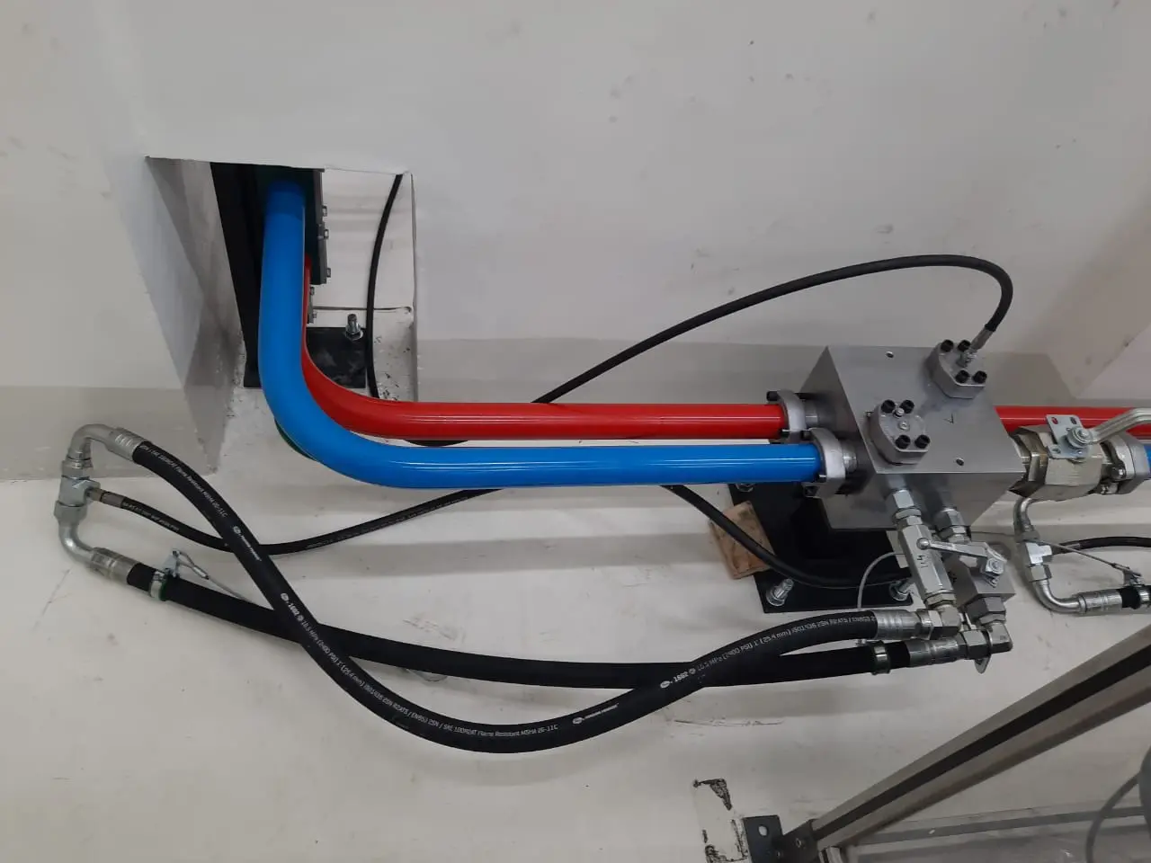
Cenergy Offshore implemented a non-welded hydraulic hardline piping system for both test systems. The solution combined two Tube-Mac non-welded technologies according to the pressure and piping requirements: a) Retain Ring Flange System for the HBBB Test Rig. b) 37° Flare Flange System for the Load Frame System
The complete system was engineered and pre-fabricated before installation. This allowed the piping to be manufactured under controlled conditions and installed at the new laboratory according to the approved design. The piping support arrangement was also designed to accommodate the system configuration and accumulator connections while making efficient use of the available space.
Because the Applied Mechanics Lab was still under construction, the project provided an opportunity to design and pre-fabricate the hydraulic piping before the facility was ready for installation.
Cenergy Offshore obtained the required site drawings and equipment information from Cummins and developed the initial Piping & Instrumentation Diagram (P&ID).
Following customer approval of the P&ID, a preliminary routing plan was developed.
Cenergy Offshore then carried out a detailed site inspection and measurement survey to verify the actual site conditions and identify any deviations from the available drawings.
The survey information was incorporated into the final design, resulting in:
This approach reduced the risk of installation conflicts once the pre-fabricated piping arrived at site.
The hydraulic pipe spools were pre-fabricated at the Tube-Mac Piping Technologies (TMI) facility in Canada based on the approved GA drawings and BOM.
Following fabrication, the piping underwent controlled cleaning and flushing before being painted and shipped to India.
The shipment included:
Items that could be sourced locally, including fasteners, supports and hoses, were procured in India to optimise project cost and delivery time.
Pre-fabrication also helped maintain consistency in pipe routing and connection quality while reducing the amount of fabrication required inside the new laboratory.
The pre-fabricated pipe spools were installed at the Cummins facility according to the approved GA drawings.
Locally procured supports were installed to match the engineered piping arrangement.
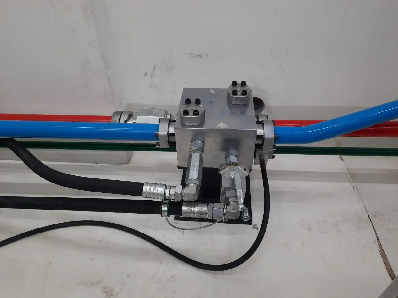
Particular attention was given to routing the hardline between the HPU room and the test rig area, as well as integrating manifold blocks and accumulator connections within the available space.
PYPLOK® end flange adapters were used where required to connect small-bore piping to valve manifold blocks.
After completion of the pipe erection, the piping joints were torqued to the specified values before pressure testing.
Once installation was complete, the hydraulic piping system underwent pressure testing using hydraulic oil.
The piping was tested to 1.5 times the respective system working pressure, with the testing witnessed by the customer.
The pressure testing verified the integrity of the installed piping and connections before the system was flushed and commissioned.
Following successful pressure testing, the hydraulic piping system was flushed to achieve the required cleanliness level.
The final cleanliness level achieved was significantly cleaner than the customer’s specified requirement, providing additional assurance for the hydraulic test equipment.
Maintaining a high level of hydraulic cleanliness was particularly important for the fatigue laboratory because contamination could affect the performance and reliability of the hydraulic equipment during repeated testing.
After completion of the flushing operation, the temporary flushing loops were dismantled and the piping was reconnected to the respective equipment ports.
The reassembled joints were re-torqued to the required values before the hydraulic equipment was operated.
The test systems were successfully commissioned and the customer positively acknowledged the completed installation through signed project reports.
Cenergy Offshore successfully delivered the complete hydraulic piping system for Cummins’ Block and Head Test Rig Fatigue Laboratory.
The project addressed the key reliability challenge associated with hydraulic piping in a high-vibration test environment by replacing conventional welded connections with a non-welded hydraulic hardline solution.
The approximately 50-metre piping system served two separate hydraulic circuits, with pressures of up to 5,800 PSI, and incorporated the required manifold and accumulator connections within the available laboratory space.
Through detailed engineering, site verification, controlled pre-fabrication, professional installation and rigorous testing and flushing, the system was successfully commissioned within the customer’s required timeline.
The completed system provided Cummins with a reliable hydraulic piping solution for its new fatigue testing facility while addressing the limitations experienced with conventional welded piping.
Hydraulic piping for Cummins Block and Head Test Rig Fatigue Laboratory
Complete design, supply, installation and commissioning
Approximately 50 metres of hydraulic piping
Two separate hydraulic systems
HBBB Test Rig: 5,800 PSI
Load Frame System: 3,000 PSI
Retain Ring Flange System for HBBB Test Rig
37° Flare Flange System for Load Frame System
Designed for a high-vibration test environment
Engineered piping and supports for accumulator connections
Detailed site survey and measurement verification
P&ID, GA drawings and final BOM developed before fabrication
Pre-fabricated pipe spools manufactured at TMI, Canada
Controlled cleaning and flushing before shipment
Pressure tested to 1.5× system working pressure
Flushed to a cleanliness level significantly exceeding the required value
Successfully commissioned and handed over within the customer's timeline
Marine Heating Coil Repair : Traditional Welding vs. Pyplok® Cold Work
Marine Heating Coil Repair : Traditional Welding vs. Pyplok® Cold Work
Piping for Water Mist System in Dwarka Expressway
Piping for Water Mist System in Dwarka Expressway
Drill Hydraulics Piping for GTRV (Fugro Voyager)
Drill Hydraulics Piping for GTRV (Fugro Voyager)

Kindly provide your details and project requirements, and our team will promptly get in touch with you to address your needs. We look forward to assisting you!